[ nodar hdk+rd ]
HDK Datasheet
Develop autonomous and 3D monitoring applications using the Hammerhead HDK + Reference Design.
10x the Range. 5x the Resolution.
The NODAR Hammerhead Development Kit (HDK) is a complete stereo vision platform for evaluating and integrating ultra-wide baseline depth perception into autonomous vehicles, robotics, and industrial automation systems. The HDK ships with automotive-grade 5.4 MP HDR stereo cameras and a ruggedized NVIDIA Orin processing unit pre-loaded with NODAR Hammerhead software, delivering color point clouds and occupancy maps out of the box.
Ultra-wide baseline stereo vision revolutionizes depth perception by expanding baseline distances from 100 mm to 1000 mm — 10 times wider than conventional setups. This extended baseline increases depth accuracy and range by a factor of 10, enabling precise 3D vision over greater distances for applications in autonomous vehicles, robotics, and industrial automation.


System Architecture
Everything You Need, Connected.
The left camera and right camera are each connected to the ruggedized Orin processing unit via 1G PoE (Power over Ethernet), enabling power and data transmission through the same cable. The ruggedized Orin is connected to the user system via 10G Ethernet, providing high-speed data transfer to the user’s computing environment. The Orin also connects to a monitor using HDMI, providing a visual interface for output. Additionally, the Orin is connected to a keyboard and mouse through USB, enabling user interaction for system control.
The NODAR Viewer can be installed on the Orin or the user computer. Note that the Viewer takes up some GPU resources, so it does reduce the frame rate when running on the Orin.

HDK Software Stack
NODAR HDK software runs on the ruggedized Orin and consists of three blocks:
● Stereo Camera Driver - captures images from two cameras.
● Auto-Exposure - automatically sets the camera exposure for both left and right cameras. The feedback loop is limited to approximately 1 second.
● HDK API - converts raw images into high-quality color point clouds and occupancy maps. Supports ROS2, ZeroMQ, and a ZeroMQ/ROS2 bridge.
The input and output topics are discussed in the linked API documentation. Data fields that can currently be recorded through the NODAR Viewer are found on the NODAR Documentation site.

Developer Resources
Everything you need to evaluate, integrate, and deploy Hammerhead in your application

HDK Datasheet
Full datasheet covering performance specifications, mounting options, and ordering information.

Quick Start Guide, Manual & Other Tools
Full technical documentation for the HDK, including API references, quick start guides, and SDK resources.
Camera Specifications
parameter
value
Class
Automotive
Format
5.4 MP HDR
Pixels
2880 x 1860
Pixel Size
3 µm
Shutter
Rolling Shutter
HDR Type
Two photodiodes and four TIAs
Dynamic Range
120 dB
Companded Bit Depth
16-bits
Exposure
86 µs to 47 ms
Gain
0 to 30 dB
Ingress Protection
IP67
Focus
Infinity
Lens
S-mount
IR Filter
650 nm
Synchronization
PTP (IEEE 1588)
Camera-to-camera timing jitter
10-µs average <20 µs
Dataflow from each camera
<1 Gbit/s (800 Mbit/s typ.)
Lens Options
option
focal lenght
ingress progression
30°
16.0mm
IP67
65°
6.8mm
IP69
135°
4.0mm
IP69
3D
Specifications
parameter
30° FOV
65° FOV
135° FOV
Horizontal field of view
30°
65°
135°
Vertical field of view
19.4°
42°
87°
Baseline B
1 m
1 m
0.5 m
Disparity search range
1024 pixels
0 to 1023 pixels
1024 pixels
0 to 1023 pixels
1024 pixels
0 to 1023 pixels
Minimum depth (Zmin)
5.23 m
2.20 m
0.65 m
Maximum depth (corresponding to ±2% relative range error)
1067 m
450 m
Disparity is related to depth by the equation $D = \frac{fB}{z}$, where $D$ is the disparity in pixels, $f$ is the focal length in pixels, $B$ is the baseline length, and $z$ is the depth to the object. Instantaneous Field of View (IFOV) is the angle subtended by one pixel.
Disparity Discretization
disparity range
30° FOV
65° FOV
135° FOV
0 to 127 pixel disparity
1/16 pixel
1/16 pixel
1/16 pixel
127 to 511 pixel disparity
1/8 pixel
1/8 pixel
1/8 pixel
511 to 1023 pixel disparity
1/4 pixel
1/4 pixel
1/4 pixel
Disparity Error
condition
30° FOV
65° FOV
135° FOV
Good weather
±0.1 pixel
±0.1 pixel
±0.1 pixel
Bad weather
(32 mm/hr heavy rain)
±0.3 pixel
±0.3 pixel
±0.3 pixel
Disparity error is median disparity when measuring a flat target.
Depth Perception - Good Weather
range
30° FOV
(1m baseline)
65° FOV
(1m baseline)
135° FOV
(0.5m baseline)
10 m
±0.8 cm
Disparity = 533 pixels
±0.8 cm
Disparity = 225 pixels
—
20 m
±1.6 cm
Disparity = 267 pixels
±1.8 cm
Disparity = 113 pixels
—
30 m
±3.4 cm
Disparity = 178 pixels
±4.0 cm
Disparity = 75 pixels
—
50 m
±4.7 cm
Disparity = 107 pixels
±11.1 cm
Disparity = 45 pixels
—
100 m
±18.8 cm
Disparity = 53 pixels
±44.4 cm
Disparity = 23 pixels
—
200 m
±75 cm
Disparity = 27 pixels
±178 cm
Disparity = 11 pixels
—
300 m
±169 cm
Disparity = 18 pixels
±400 cm
Disparity = 8 pixels
—
Depth precision is range-dependent and derived from the disparity error according to $dz = \frac{z^2}{fB}\times\text{pixel error}$, where $f$ is the focal length in pixels, $B$ is the baseline length, and $z$ is the depth to the object. Multiple by 3 for bad weather.
30° FOV
(1m baseline)
65° FOV
(1m baseline)
135° FOV
(0.5m baseline)
Instantaneous Field of View (IFOV)
0.01°
0.026°
0.043°
Focal length
f = 1/IFOV
5333 pixels
2250 pixels
1333 pixels
Lateral Resolution
range
30° FOV
(1m baseline)
65° FOV
(1m baseline)
10 m
0.2 cm
0.4 cm
20 m
0.4 cm
0.9 cm
30 m
0.7 cm
1.5 cm
50 m
0.9 cm
2.2 cm
100 m
1.9 cm
4.4 cm
200 m
3.8 cm
8.9 cm
300 m
5.6 cm
13.3 cm
500 m
9.4 cm
22.2 cm
1000 m
18.8 cm
44.4 cm
Minimum Detectable Object Size
(Tire on Road)
30° FOV
TP 50%
30° FOV
TP 80%
30° FOV
TP 90%
65° FOV
TP 50%
65° FOV
TP 80%
65° FOV
TP 90%
10 m
1 cm
1 cm
2 cm
2 cm
3 cm
4 cm
20 m
2 cm
3 cm
4 cm
4 cm
6 cm
9 cm
30 m
3 cm
4 cm
6 cm
7 cm
9 cm
13 cm
50 m
5 cm
7 cm
9 cm
11 cm
16 cm
22 cm
100 m
9 cm
13 cm
19 cm
22 cm
31 cm
44 cm
150 m
14 cm
20 cm
28 cm
33 cm
47 cm
67 cm
200 m
19 cm
26 cm
38 cm
44 cm
62 cm
89 cm
300 m
28 cm
39 cm
56 cm
67 cm
93 cm
133 cm
Minimum detectable object size of a tire on a road using 1-m baseline and GridDetect. GridDetect uses a particle filter approach and is a recursive filter like a Kalman filter so that the tracker state at frame "t" has all the accumulated information up to that frame. For practical purposes, it can be thought to integrate over approximately three frames. The ranges corresponding to true positive (TP) detection probabilities of 50, 80, and 90% are reported for a tire on a road. The TP detection range increases with higher contrast objects and depends on the number of pixels on the target, with 50% corresponding to 5 x 5 pixels, 80% corresponding to 7 x 7 pixels, and 90% corresponding to 10 x 10 pixels.
The minimum detectable object size with high confidence is 7 pixels wide. According to the table, the thinnest object at 100-m range is 13-cm wide using the 30° FOV lenses.
The smallest height object at 150 meters is 7 pixels high, or 26 cm, using 30° FOV lenses (see table for the minimum detectable object size).
Calibration
Continuous Autocalibration, Every Frame
Hammerhead applies continuous per-frame online calibration to maintain stereo alignment under vibration, temperature change, and mechanical drift. Hammerhead also offers a factory calibration routine that can be run at the factory or whenever there is a large uncertainty of the camera extrinsic parameters. Extrinsic parameters are automatically calibrated; intrinsic parameters are currently not calibrated.
Factory Calibration
parameter
value
Run time
30 seconds
Maximum relative angular search range
3°
Absolute range calibration
✓
Factory Calibration
parameter
30° FOV
65° FOV
Update rate
Every frame
Every frame
Maximum relative angular search range per frame
0.05°
0.125°
Vibration bandwidth
∞ Hz
∞ Hz
For cars, the vibration bandwidth exceeds the Nyquist rate of the camera. For example, engine vibrations may be between 100-300 Hz, which far exceed the standard video frame rates of 10, 15, 20, 30, and 60 Hz. Therefore, calibration every frame is required for calibration because it is not possible to interpolate the extrinsic camera parameters between multiple frames.
Although our calibration can handle any perturbation speed, the captured images become blurred with excessive vibration amplitude, and blurring gradually degrades stereo matching performance. In practice, with short camera exposure time with respect to the angular perturbation rate, the blurring effect is small, and the vibration is negligible and can largely be disregarded.
Mechanical, Electrical, and Environmental Specifications
Stereo Camera
parameter
value
Camera-to-Camera Spacing
1 m
Dimensions
97 x 173 x 1100 mm
Power Consumption per Camera
3.1 W
Compliance
CE, FCC, RoHS, REACH, WEEE
Storage Temperature
-30 to 60°C
Operating Temperature
-20 to 55°C ambient
Humidity
Operating: 20% ~ 80%, relative, non-condensing
Shock and Vibration
DIN EN 60068-2-27, DIN EN 60068-2-64, DIN EN 60068-2-6
Industrial EMC Immunity
DIN EN 61000-6-2
Ingress protection
Built to IP67
Hermetically sealed
No
M12-to-RJ45 cable length
(2 cables from stereo camera to the Orin)
15 m
Computer
parameter
Value
Operating Temperature
-25°C to 55°C
Regulatory Certifications
CE, FCC, ROHS, UKCA
Shock/Vibration Rating
IEC 60068-2-64 IEC 60068-2-27
DC Power Input Range
9VDC~36VDC (≤130W)
Power Connector
DC Power input via 4-Pin DIN Molding Style Connector
Weight
item
weight
Stereo camera (1-m baseline)
7.4 lbs
Ruggedized computer
4 to 9.4 lbs (depending on exact model)
Computer power supply
2.6 lbs
Two rugged ethernet cables
(M12-to-RJ45, 15-m length)
3.4 lbs
Shipping box with components: 33 lbs, 48 x 16.5 x 11.5 inches
Mounting Configurations
The HDK sensor bar supports three mounting configurations. The bottom center has a 1/4"-20 threaded hole for tripod use. Four additional 1/4"-20 threaded holes at the bar ends are used for vehicle or infrastructure mounts.
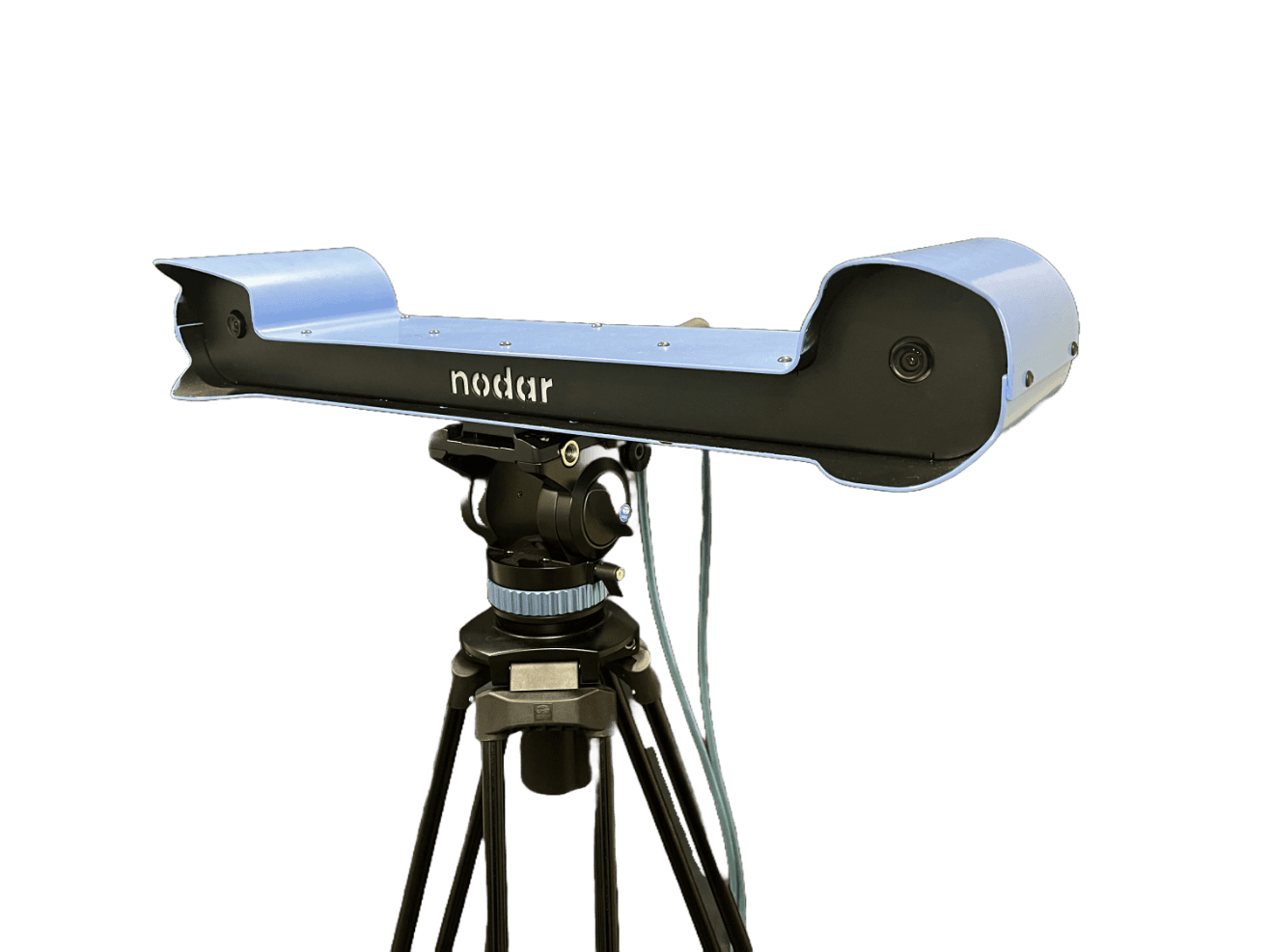
Tripod Mount

Mount the center threaded hole to a standard camera tripod. A solid, smooth-motion tripod is recommended. The tripod shown in the image above is the SIRUI AM-25S professional heavy-duty tripod.
item
make
model
quantity
Vehicle Roof Mount

The bottom of the HDK bar has four 1/4-20” threaded holes on the left and right ends. Two of the threaded holes are used for eyebolts for safety straps, and two are used for magnetic or suction cup mounts with ball heads.
item
make
model
quantity
Infrastructure Mount

Two threaded holes on the back of the enclosure allow attachment to walls or fixed structures. To securely attach the sensor head, we recommend RAM mounts or similar mounts.
item
make
model
quantity
Hardware Reference Design and SDK
The HDK hardware design is available for licensing and seamless integration into your product ecosystem. Each reference design includes a comprehensive technical package:
● CAD Models: Native SolidWorks files for easy modification.
● Manufacturing Instructions: Detailed assembly drawings and instructional videos for manufacturing.
● Full BOM: A complete Bill of Materials covering hardware, optics, cables, and computing components.
Licensing grants a non-exclusive, worldwide, perpetual right to modify and deploy these designs within your own hardware products. See the Reference Design License Term Sheet for details.

NODAR SDK
The NODAR SDK includes example code for interfacing with the HDK using ROS2 and ZMQ. Full documentation is available in the HDK Communication section and the SDK documentation in our GitHub repository.
Ordering Information
Part Number Structure
NDR-HDK-2.0-xxx-yy[-A]
• xxx = 50 for 50-cm baseline | xxx = 100 for 100-cm baseline | xxx = U for an untethered system
• yy = 30 for 30° FOV | yy = 65 for 65° FOV | yy = 135 for 135° FOV
• Add -A to include the ruggedized Orin computer
Example Part Numbers
part number
description
NDR-HDK-2.0-100-65
The Hammerhead Development Kit v2.0 with 1m baseline and 65° FOV lenses. Sensor head only - no computer.
NDR-HDK-2.0-100-30
The Hammerhead Development Kit v2.0 with 1m baseline and 30° FOV lenses. Sensor head only - no computer.
NDR-HDK-2.0-100-65-A
The Hammerhead Development Kit v2.0 with 1m baseline and 65° FOV lenses and ruggedized Orin computer.
NDR-HDK-2.0-U-65-A
The Hammerhead Development Kit v2.0 with untethered cameras, 65° FOV lenses and ruggedized Orin computer.
NDR-HDK-2.0-A
Orin AGX computer with Hammerhead software.
NDR-HW-REF-2.0
Hardware reference design with license.
Bill of Materials
NDR-HDK-2.0-xxx-yy
item
description
Quantity
1
Stereo camera IP67 5.4 MP
1
2
2
3
1
NDR-HDK-2.0-xxx-yy-A
item
description
Quantity
1
Stereo camera IP67 5.4 MP
1
2
2
3
1
4
Ruggedized AGX Orin computer
1
5
AGX Orin power supply
1
6
OWC 10gb ethernet to usb adapter
1
HDK Communication Interface
The Hammerhead Development Kit (HDK) offers several communication options enabling integration into diverse applications, including ROS2, ZeroMQ, and the ZeroMQ/ROS2 Bridge. ZeroMQ is more efficient for data transmission. For ROS2, we recommend using the ZeroMQ/ROS2 Bridge as it optimizes bandwidth and data transfer. Follow the links for details.
1. Interaction Via ZeroMQ
2. Interaction Via ROS2
3. Interaction Via the ZeroMQ/ROS2 Bridge: If using ROS2, but experiencing high network latency or low throughput, consider using the ZeroMQ/ROS2 Bridge. This layer acts a middleman, enabling images and point clouds to be sent over the network using ZeroMQ, and then reconstructed for ROS2 on the local machine. This circumvents possible network issues introduced by the ROS2 middleware. An example demonstrating how to interact with the HDK using this mechanism is provided here. If using the bridge, set the communicationlib field in masterconfig.ini to zmq.